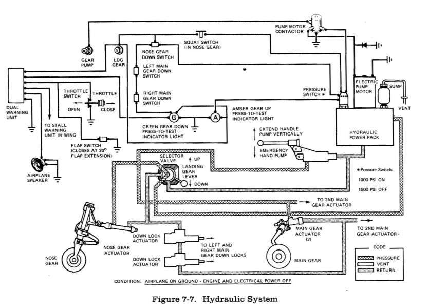
Hydraulic power (see figure 7-7) is supplied by an electrically-driven hydraulic power pack located behind the firewall between the pilot's and copilot's rudder pedals. The power pack's only function is to supply hydraulic power for operation of the retractable landing gear. This is accomplished by applying hydraulic pressure to actuator cylinders which extend or retract the gear. The hydraulic system normally operates at 1000 PSI to 1500 PSI, and is protected by relief valves which prevent high pressure damage to the pump and other components in the system. The electrical portion of the power pack is protected by a 30-amp push-pull type circuit breaker switch, labeled GEAR PUMP, on the left switch and control panel.
The hydraulic power pack is turned on by a pressure switch on the power pack when the landing gear lever is placed in either the GEAR UP or GEAR DOWN position. When the lever is placed in the GEAR UP or GEAR DOWN position, it mechanically rotates a selector valve which applies hydraulic pressure in the direction selected. As soon as the landing gear reaches the selected position, a series of electrical switches will illuminate one of two indicator lights on the instrument panel to show gear position and completion of the cycle. After indicator light illumination, (GEAR DOWN cycle only), hydraulic pressure will continue to build until the power pack pressure switch turns the power pack off.
The hydraulic system includes an emergency hand pump to permit manual extension of the landing gear in the event of hydraulic power pack failure. The hand pump is located on the cabin floor between the front seats.
During normal operations, the
landing gear should require from 5 to 7 seconds to fully extend or retract. For
malfunctions of the hydraulic and landing gear systems, refer to Section 3 of
this handbook.
The airplane has a single-disc, hydraulically-actuated brake on each main landing gear wheel. Each brake is connected, by a hydraulic line, to a master cylinder attached to each of the pilot's rudder pedals. The brakes are operated by applying pressure to the top of either the left (pilot's) or right (copilot's) set of rudder pedals, which are interconnected. When the airplane is parked, both main wheel brakes may be set by utilizing the parking brake which is operated by a handle below the left side of the switch and control panel. To apply the parking brake, set the brakes with the rudder pedals, pull the handle aft, and rotate it 900 down.
For maximum brake life, keep the brake system properly maintained, and minimize brake usage during taxi operations and landings.
Some of the symptoms of impending brake failure are: gradual decrease in braking action after brake application, noisy or dragging brakes, soft or spongy pedals, and excessive travel and weak braking action. If any of these symptoms appear, the brake system is in need of immediate attention. If, during taxi or landing roll, braking action decreases, let up on the pedals and then re-apply the brakes with heavy pressure. If the brakes, become spongy or pedal travel increases, pumping the pedals should build braking pressure. If one brake becomes weak or fails, use the other brake sparingly while using opposite rudder, as required, to offset the good brake.