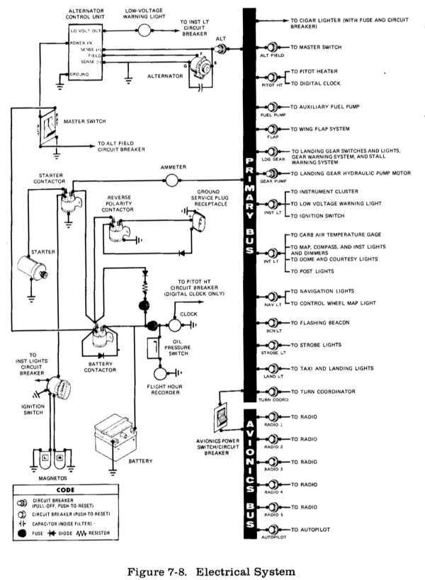
The airplane is equipped with a 28-volt, direct-current electrical system (see figure 7-8). The system uses a battery, located aft of the rear cabin wall, as the source of electrical energy and a belt-driven 60-amp alternator to maintain the battery's state of charge. Power is supplied to most general electrical and all avionics circuits through the primary bus bar and the avionics bus bar, which are interconnected by an avionics power switch. The primary bus bar is on anytime the master switch is turned on, and is not affected by starter or external power usage. Both bus bars are on anytime the master and avionics power switches are on.
The master switch is a split-rocker type switch labeled MASTER, and is ON in the up position and off in the down position. The right half of the switch, labeled BAT, controls all electrical power to the airplane. The left half, labeled ALT, controls the alternator.
Normally, both sides of the
master switch should be used simultane ously; however the BAT side of the switch
could be turned ON separately to check equipment while on the ground. To check
or use avionics equipment or radios while on the ground, the avionics power
switch must be turned ON. The ALT side of the switch, when placed in the off
position, removes the alternator from the electrical system. With this switch in
the off position, the entire electrical load is placed on the battery. Continued
operation with the alternator switch in the off position will reduce battery
power low enough to open the battery contactor, remove power from the alternator
field, and prevent alternator restart.
Electrical power from the
airplane primary bus to the avionics bus (see figure 7-8) is controlled by a
single-rocker switch/circuit breaker labeled AVN PWR. The switch is located on
the left sidewall avionics circuit breaker panel and is ON in the up position
and OFF in the down position. With the switch in the OFF position, no electrical
power will be applied to the avionics equipment, regardless of the position of
the master switch or the individual equipment switches. The avionics power
switch also functions as a circuit breaker. If an electrical malfunction should
occur and cause the circuit breaker to open, electrical power to the avionics
equipment will be interrupted and the switch will automatically move to the OFF
position. If this occurs, allow the circuit breaker to cool approxi mately two
minutes before placing the switch in the ON position again. If the circuit
breaker opens again, do not reset it. The avionics power switch should be placed
in the OFF position prior to turning the master switch ON or off, starting the
engine, or applying an external power source, and may be utilized in place of
the individual avionics equipment switches.
The ammeter, located beneath the
fuel gages, indicates the amount of current, in amperes, from the alternator to
the battery or from the battery to the airplane electrical system. When the
engine is operating and the master switch is turned on, the ammeter indicates
the charging rate applied to the battery. In the event the alternator is not
functioning or the electrical load exceeds the output of the alternator, the
ammeter indicates the battery discharge rate.
ALTERNATOR CONTROL UNIT AND LOW-VOLTAGE WARNING LIGHT
The airplane is equipped with a combination alternator regulator high-low voltage control unit mounted on the engine side of the firewall and a red warning light labeled LOW VOLTAGE, on the left side of the instrument panel adjacent to the manifold pressure gage.
In the event an over-voltage condition occurs, the alternator control unit automatically removes alternator field current which shuts down the alternator. The battery will then supply system current as shown by a discharge rate on the ammeter. Under these conditions, depending on electrical system load, the low-voltage warning light will illuminate when system voltage drops below normal. The alternator control unit may be reset by turning the master switch off and back on again. If the warning light does not illuminate, normal alternator charging has resumed; however, if the light does illuminate again, a malfunction has occurred, and the flight should be terminated as soon as practicable.
NOTE
Most of the electrical circuits
in the airplane are protected by "push-to reset" type circuit breakers mounted
on the lower left side of the switch and control panel. However, a "pull-off"
type circuit breaker protects alternator output and the landing gear system
hydraulic pump motor circuit. In addition to the individual circuit breakers, a
single-rocker switch/circuit breaker, labeled AVN PWR on the avionics panel,
located on the left cabin sidewall between the forward doorpost and the switch
and control panel, also protects the avionics systems. The cigar lighter is
protected by a manually-reset type circuit breaker on the back of the lighter,
and a fuse behind the instrument panel. The control wheel map light (if
installed) is protected by the NAy LIGHTS circuit breaker and a fuse behind the
instrument panel. Electrical circuits which are not protected by circuit
breakers are the battery contactor closing (external power) circuit, clock
circuit, and flight hour recorder circuit. These circuits are protected by fuses
mounted adjacent to the battery.
GROUND SERVICE PLUG RECEPTACLE
A ground service plug receptacle may be installed to permit the use of an external power source for cold weather starting and during lengthy maintenance work on the electrical and electronic equipment. Details of the ground service plug receptacle are presented in Section 9, Supplements.