Conventional navigation lights are located on the wing tips and top of the rudder. Dual landing/taxi lights are located in the cowl nose cap. Additional lighting is available and includes a flashing beacon mounted on top of the vertical fin, a strobe light on each wing tip, and a courtesy light recessed into the lower surface of each wing slightly outboard of the cabin doors. Details of the strobe light system are presented in Section 9. Supplements. The courtesy lights are operated by the DOME LIGHTS switch located on the overhead console; push the switch to the right to turn the lights on. The remaining exterior lights are operated by rocker switches located on the left switch and control panel; push the rocker up to the ON position.
The flashing beacon should not
be used when flying through clouds or overcast; the flashing light reflected
from water droplets or particles in the atmosphere, particularly at night, can
produce vertigo and loss or orienta tion.
Instrument panel and switch and control panel lighting is providedby flood lighting, integral lighting, and post lighting (if installed). Lighting intensity is controlled by a dual dimming rheostat equipped with an outer knob labeled PANEL LT, and an inner knob labeled RADIO LT, located below the throttle. A slide-type switch (if installed) on the overhead console, labeled PANEL LIGHTS, is used to select flood lighting in the FLOOD position, post lighting in the POST position, or a combination of post and flood lighting in the BOTH position.
Instrument panel and switch and control panel flood lighting consists of a single red flood light in the forward edge of the overhead console. To use flood lighting, move the slide switch in the overhead console, labeled PANEL LIGHTS, to the FLOOD position and rotate the outer knob on the light dimming rheostat, labeled PANEL LT, clockwise to the desired light intensity.
Post lights (if installed) are mounted at the edge of each instrument and provide direct lighting. To use post lighting, move the slide switch in the overhead console, labeled PANEL LIGHTS, to the POST position and rotate the outer knob on the light dimming rheostat, labeled PANEL LT, clockwise to obtain the desired light intensity. When the PANEL LIGHTS switch is placed in the BOTH position, the flood lights and post lights will operate simultaneously.
The engine instrument cluster, radio equipment, digital clock and magnetic compass have integral lighting and operate independently of post or flood lighting. The intensity of instrument cluster, radio, and digital clock lighting is controlled by the inner knob on the light dimming rheostat labeled RADIO LT; compass lighting is controlled by the outer knob labeled PANEL LT. Rotate the knobs clockwise to obtain the desired light intensity. However, for daylight operation, the engine instrument, digital clock and compass lights may be turned off while still maintaining maximum light intensity for the digital readouts in the radio equipment. This is accomplished by rotating the knobs full counterclockwise. The flood lightslpost lights are also turned off for daylight operation by rotating the PANEL LT knob full counterclockwise.
A cabin dome light, in the aft part of the overhead console, is operated by a switch near the light. To turn the light on, move the switch to the right.
A control wheel map light is available and is mounted on the bottom of the pilot's control wheel. The light illuminates the lower portion of the cabin just forward of the pilot and is helpful when checking maps and other flight data during night operations. To operate the light, first turn on the NAV LT switch; then adjust the map light's intensity with the knurled disk type rheostat control located at the bottom of the control wheel.
A doorpost map light is located on the left forward doorpost. It contains both red and white bulbs and may be positioned to illuminate any area desired by the pilot. The light is controlled by a switch, below the light, which is labeled RED, OFF, and WHITE. Placing the switch in the top position will provide a red light. In the bottom position, standard white lighting is provided. In the center position, the map light is turned off. Red light intensity is controlled by the outer knob on the light dimming rheostat labeled PANEL LT.
The most probable cause of a
light failure is a burned out bulb; however, in the event any of the lighting
systems fail to illuminate when turned on, check the appropriate circuit
breaker. If the circuit breaker has opened (white button popped out), and there
is no obvious indication of a short circuit (smoke or odor), turn off the light
switch of the affected lights, reset the breaker, and turn the switch on again.
If the breaker opens again, do not reset it.
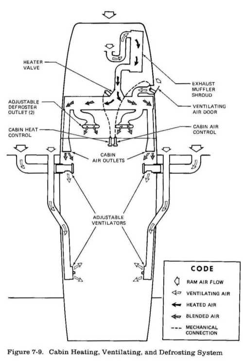
CABIN HEATING, VENTILATING AND DEFROSTING SYSTEM
Heated air from a muffler shroud and heater valve and ventilating air from an external ventilating air door are supplied to a manifold just forward of the pilot's and copilot's feet (see figure 7-9). The temperature and volume of airflow to the manifold and then to the cabin is regulated by manipulation of the push-pull CABIN HEAT and CABIN AIR controls. Both controls permit intermediate settings.
Cabin heat and ventilating air from the manifold to the cabin is supplied by two ducts, one extending down each side of the cabin to an outlet at the front door post at floor level. Windshield defrost air is also supplied by dual ducts leading from the cabin manifold to outlets on top of the glare shield. Two knobs on each outlet control sliding valves which permit regulation of defroster airflow.
For cabin ventilation, pull the CABIN AIR knob out, with the CABIN HEAT knob pushed full in. To raise the air temperature, pull the CABIN HEAT knob out until the desired temperature is attained. Additional heat is available by pulling the knob out farther; maximum heat is available with the CABIN HEAT knob pulled out and the CABIN AIR knob pushed full in.
NOTE