PITOT-STATIC SYSTEM AND INSTRUMENTS
The pitot-static system supplies ram air pressure to the airspeed indicator and static pressure to the airspeed indicator, vertical speed indicator and altimeter. The system is composed of either an unheated or heated pitot tube mounted on the lower surface of the left wing, two external static ports on the left and right sides of the forward fuselage, and the associated plumbing necessary to connect the instruments to the sources.
The heated pitot system (if installed) consists of a heating element in the pitot tube, a rocker switch labeled PITOT HT and a 10-amp push-to reset circuit breaker on the left side of the switch and control panel, and associated wiring. When the pitot heat switch is turned on, the element in the pitot tube is heated electrically to maintain proper operation in possible icing conditions. Pitot heat should be used only as required.
A static pressure alternate source valve may be installed beneath the throttle, and can be used if the external static source is malfunctioning. This valve supplies static pressure from inside the cabin instead of tbe external static ports.
If erroneous instrument readings are suspected due to water or ice in the pressure line going to the standard external static pressure source, the alternate static source valve should be pulled on.
Pressures within the cabin will
vary with heater/vents opened or closed and windows open. Refer to Sections 3
and 5 for the effect of varying cabin pressures on airspeed and altimeter
readings.
The airspeed indicator is calibrated in knots and miles per hour. Limitation and range markings (in KIAS) include the white arc (42 to 100 knots), green arc (50 to 145 knots), yellow arc (145 to 164 knots), and a red line (164 knots).
If a true airspeed indicator is
installed, it is equipped with a rotatable ring which works in conjunction with
the airspeed indicator dial in a manner similar to the operation of a flight
computer. To operate the indicator, first rotate the ring until pressure
altitude is aligned with outside air temperature in degrees Fahrenheit. Pressure
altitude should not be confused with indicated altitude. To obtain pressure
altitude, momentarily set the barometric scale on the altimeter to 29.92 and
read pressure altitude on the altimeter. Be sure to return the altimeter baromet
ric scale to the original barometric setting after pressure altitude has been
obtained. Having set the ring to correct for altitude and temperature, read the
true airspeed shown on the rotatable ring by the indicator pointer. For best
accuracy, the indicated airspeed should be corrected to calibrated airspeed by
referring to the Airspeed Calibration chart in Section 5. Knowing the
calibrated airspeed, read true airspeed on the ring opposite the calibrated
airspeed.
The vertical speed indicator
depicts airplane rate of climb or descent in feet per minute. The pointer is
actuated by atmospheric pressure changes resulting from changes of altitude as
supplied by the static source.
Airplane altitude is depicted by
a barometric type altimeter. A knob near the lower left portion of the indicator
provides adjustment of the instrument's barometric scale to the current
altimeter setting.
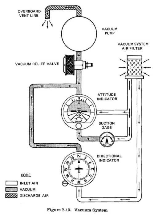
An engine-driven vacuum system
(see figure 7-10) provides the suction necessary to operate the attitude
indicator and directional indica tor. The system consists of a vacuum pump
mounted on the engine, a vacuum relief valve and vacuum system air filter on the
aft side of the firewall below the instrument panel, instruments on the left
side of the instrument panel and a suction gage on the right side of the
panel.
An attitude indicator is
available and gives a visual indication of flight attitude. Bank attitude is
presented by a pointer at the top of the indicator relative to the bank scale
which has index marks at 10 deg, 2O deg, 30 deg, 60 deg,
and 900 either side of the center mark. Pitch
and roll attitudes are presented by a miniature airplane superimposed over a
symbolic horizon area divided into two sections by a white horizon bar. The
upper "blue sky" area and the lower "ground" area have arbitrary pitch reference
lines useful for pitch attitude control. A knob at the bottom of the instrument
is provided for in- flight adjustment of the miniature airplane to the horizon
bar for a more accurate flight attitude indication.
A directional indicator displays
airplane heading on a compass card in relation to a fixed simulated airplane
image and index. The directional indicator will precess slightly over a period
of time. Therefore, the compass card should be set in accordance with the
magnetic compass just prior to takeoff, and occasionally re-adjusted on extended
flights. A knob on the lower left edge of the instrument is used to adjust the
compass card to correct for any precession.
The suction gage, located at the upper right corner of the instrument panel, is calibrated in inches of mercury and indicates suction available for operation of the attitude and directional indicators. The desired suction range is 4.5 to 5.4 inches of mercury. A suction reading below this range may indicate a system malfunction or improper adjustment, and in this case, the indicators should not be considered reliable.