The airplane is equipped with a vane-type stall warning unit, in the leading edge of the left wing, which is electrically connected to a dual warning unit located behind the instrument panel. The vane in the wing senses the change in airflow over the wing, and operates the dual warning unit, which produces a continuous tone over the airplane speaker at airspeeds between 5 and 10 knots above the stall in all configurations.
If the airplane has a heated stall warning system, the vane and sensor unit in the wing leading edge is equipped with a heating element. The heated part of the system is operated by the PITOT NT switch, and is protected by the PITOT HT circuit breaker.
The stall warning system should
be checked during the pre-flight inspection by momentarily turning on the master
switch and actuating the vane in the wing. The system is operational if a
continuous tone is heard on the airplane speaker as the vane is pushed
upward.
If the airplane is equipped with
avionics, various avionics support equipment may also be installed. Equipment
available includes two types of audio control panels, microphone-headset
installations and control surface static dischargers. The following paragraphs
discuss these items. Description and operation of radio equipment is covered in
Section 9 of this handbook.
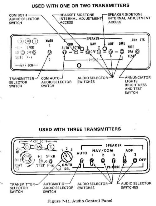
Two types of audio control
panels (see figure 7-11) are available for this airplane, depending upon how
many transmitters are included. The operational features of both audio control
panels are similar and are discussed in the following paragraphs.
When the avionics package includes a maximum of two transmitters, a two-position toggle-type switch, labeled XMTR, is provided to switch the microphone to the transmitter the pilot desires to use. If the airplane avionics package includes a third transmitter, the transmitter selector switch is a three-position rotary-type switch, labeled XMTR SEL. The numbers 1, 2, or 1, 2 and 3 adjacent to the selector switches correspond to the first, second and third (from top to bottom) transmitters in the avionics stack. To select a transmitter, place the transmitter selector switch in the position number corresponding to the desired transmitter.
The action of selecting a
particular transmitter using the transmitter selector switch simultaneously
selects the audio amplifier associated with that transmitter to provide speaker
audio. For example, if the number one transmitter is selected, the audio
amplifier in the number one NAV/ COM is also selected and is used for ALL
speaker audio. In the event the audio amplifier in use fails, as evidenced by
loss of all speaker audio, selecting an alternate transmitter will reestablish
speaker audio using the alternate transmitter audio amplifier. Headset audio is
not affected by audio amplifier operation.
Both audio control panels (see figure 7-11) incorporate three-position toggle-type audio selector switches for individual control of the audio from systems installed in the airplane. These switches allow receiver audio to be directed to the airplane speaker or to a headset, and heard singly or in combination with other receivers. To hear a particular receiver on the airplane speaker, place that receiver's audio selector switch in the up (SPEAKER) position. To listen to a receiver over a headset, place that receiver's audio selector switch in the down (PHONE) position. The center (OFF) position turns off all audio from the associated receiver.
Volume level is adjusted using the individual receiver volume controls on each radio.
A special feature of the audio control panel used when one or two transmitters are installed is separate control of NAV and COM audio from the NAV/COM radios. With this installation, the audio selector switches labeled NAy, 1 and 2 select audio from the navigation receivers of the NAV/COM radios only. Communication receiver audio is selected by the switches labeled COM, AUTO and BOTH. Description and operation of these switches is described in later paragraphs.
When the audio control panel for
three transmitters is installed, audio from both NAy and COM frequencies is
combined, and is selected by the audio selector switches labeled NAV/COM 1, 2
and 3.
COM AUTO AUDIO SELECTOR SWITCH
The audio control panel used
with either one or two transmitters incorporates a three-position toggle switch,
labeled COM AUTO, which is provided to automatically match the audio of the
appropriate NAV/ COM communications receiver to the transmitter selected by the
transmitter selector switch. When the COM AUTO selector switch is placed in the
up (SPEAKER) position, audio from the communications receiver selected by the
transmitter selector switch will be heard on the airplane speaker. Switching the
transmitter selector switch to the other transmitter auto matically switches the
other communications receiver audio to the speaker. This automatic audio
switching feature may also be utilized when listening on a headset by placing
the GOM AUTO switch in the down (PHONE) position. If automatic audio selection
is not desired, the COM AUTO selector switch should be placed in the center
(OFF) position.
COM BOTH AUDIO SELECTOR SWITCH
The audio control panel used with either one or two transmitters incorporates a three-position toggle switch, labeled COM BOTH, which is provided to allow both COM receivers to be monitored at the same time. For example, if the COM AUTO switch is in the SPEAKER position, with the transmitter selector switch in the number one transmitter position, number one communications receiver audio will be heard on the airplane speaker. If it is also desired to monitor the number two communications receiver audio without changing the position of the transmitter selector switch, place the COM BOTH selector switch in the up (SPEAKER) position so that the number two communications receiver audio will be heard in addition to the number one communications receiver audio. This feature can also be used when listening on a headset by placing the COM BOTH audio selector switch in the down (PHONE) position.
NOTE
The audio control panel used with three transmitters incorporates a three-position toggle switch, labeled AUTO, which is provided to automat ically match the audio of the appropriate NAV/ COM receiver to the selected transmitter. To utilize this automatic feature, leave all NAV/ GOM audio selector switches in the center (OFF) position, and place the AUTO selector switch in either the SPEAKER or PHONE position, as desired. Once the AUTO selector switch is positioned, the pilot may then select any transmitter and its associated NAV/OOM receiver audio simultaneously with the transmitter selector switch. If automatic audio selection is not desired, the AUTO selector switch should be placed in the center (OFF) position.
If the NAV/COM audio selector
switch corresponding to the selected transmitter is in the PHONE position with
the AUTO selector switch in the SPEAKER position, all audio selector switches
placed in the PHONE position will automatically be connected to both the
airplane speaker and any headsets in use.
ANNUNCIATOR LIGHTS BRIGHTNESS AND TEST SWITCH
The audio control panel used
with either one or two transmitters incorporates a three-position toggle-type
switch to control the brightness level of the marker beacon indicator lights
(and certain other annunciator lights associated with avionics equipment). When
the switch is placed in the center (DAY) position, the indicator lights will
show full bright. When this switch is placed in the up (NITE) position, the
lights are set to a reduced level for typical night operations and can be
further adjusted using the RADIO LT dimming rheostat knob. The down (TEST)
position illuminates all lamps (except the ARC light in the NAV indicators)
which are controlled by the switch to the full bright level to verify lamp
operation.
Cessna radios are equipped with
sidetone capability (monitoring of the operator's own voice transmission). While
adjusting sidetone, be aware that if the sidetone volume level is set too high,
audio feedback (squeal) may result when transmitting.
When the airplane has one or two
transmitters, sidetone is provided in both the speaker and headset anytime the
COM AUTO selector switch is utilized. Placing the COM AUTO selector switch in
the OFF position will eliminate sidetone. Sidetone internal adjustments are
available to the pilot through the front of the audio control panel (see figure
7-11). Adjustment can be made by removing the appropriate plug-button from the
audio control panel (left button for headset adjustment and right button for
speaker adjustment), inserting a small screwdriver into the adjustment
potentiometer and rotating it clockwise to increase the sidetone volume
level.
When the airplane has three transmitters, sidetone will be heard on either the speaker or a headset as selected with the AUTO selector switch. Sidetone may be eliminated by placing the AUTO selector switch in the OFF position, and utilizing the individual audio selector switches. Adjust ment of speaker and headset sidetone volume can only be accomplished by adjusting the sidetone potentiometers located inside the audio control panel.
NOTE
MICROPHONE-HEADSET
INSTALLATIONS
Three types of microphone-headset installations are offered. The standard system provided with avionics equipment includes a hand-held microphone and separate headset. The keying switch for this microphone is on the microphone. Two optional microphone-headset installations are also available; these feature a single-unit microphone-headset combina tion which permits the pilot to conduct radio communications without interrupting other control operations to handle a hand-held microphone. One microphone-headset combination is offered without a padded headset and the other version has a padded headset. The microphone-headset combinations utilize a remote keying switch located on the left grip of the pilot's control wheel. The microphone and headset jacks are located on the left side of the instrument panel. Audio to all three headsets is controlled by the individual audio selector switches and adjusted for volume level by using the selected receiver volume contols.
NOTE
If frequent IFR flights are planned, installation of wick-type static dischargers is recommended to improve radio communications during flight through dust or various forms of precipitation (rain, snow or ice crystals). Under these conditions, the build-up and discharge of static electricity from the trailing edges of the wings, rudder, elevator, propeller tips, and radio antennas can result in loss of usable radio signals on all communications and navigation radio equipment. Usually the ADF is first to be affected and VHF communication equipment is the lasttobe affected.
Installation of static dischargers
reduces interference from precipita tion static, but it is possible to encounter
severe precipitation static conditions which might cause the loss of radio signals,
even with static dischargers installed. Whenever possible, avoid known severe
precipita tion areas to prevent loss of dependable radio signals. If avoidance
is impractical, minimize airspeed and anticipate temporary loss of radio signals
while in these areas.