This section provides
description and operation of the airplane and its systems. Some equipment
described herein is optional and may not be installed in the airplane. Refer to
Section 9, Supplements, for details of other optional systems and
equipment.
The airplane is an all-metal, four-place, high-wing, single-engine airplane equipped with retractable tricycle landing gear and designed for general utility purposes.
The construction of the fuselage is a conventional formed sheet metal bulkhead, stringer, and skin design referred to as semimonocoque. Major items of structure are the front and rear carry-through spars to which the wings are attached, a bulkhead with attaching plates at the base of the forward doorposts for the lower attachment of the wing struts, and the forgings and structure for the retractable main landing gear in the lower aft portion of the fuselage center section. Four engine mount stringers are also attached to the forward doorposts and extend forward to the firewall. A tunnel incorporated into the fuselage structure below the engine, in front of the firewall, is required for the forward retracting nose wheel.
The externally braced wings, containing the fuel tanks, are con structed of a front and rear spar with formed sheet metal ribs, doublers, and stringers. The entire structure is covered with aluminum skin. The front spars are equipped with wing-to-fuselage and wing-to-strut attach fit tings. The aft spars are equipped with wing-to-fuselage attach fittings, and are partial-span spars. Conventional hinged ailerons and single-slot type flaps are attached to the trailing edge of the wings. The ailerons are constructed of a forward spar containing balance weights, formed sheet metal ribs and "V" type corrugated aluminum skin joined together at the trailing edge. The flaps are constructed basically the same as the ailerons, with the exception of balance weights and the addition of a formed sheet metal leading edge section.
The empennage (tail assembly)
consists of a conventional vertical stabilizer, rudder, horizontal stabilizer,
and elevator. The vertical stabil izer consists of a forward and aft spar,
formed sheet metal ribs and reinforcements, a wrap-around skin panel, formed
leading edge skin, and a dorsal. The rudder is constructed of a formed leading
edge skin containing hinge halves, a center wrap-around skin panel, ribs, an aft
wrap-around skin panel which is joined at the trailing edge of the rudder by a
filler strip. and a ground adjustable trim tab at the base of the trailing edge.
The top of the rudder incorporates a leading edge extension which contains a
balance weight. The horizontal stabilizer is constructed of a forward and aft
spar, ribs and stiffeners, center upper and lower skin panels, left and right
upper and lower skins panels, and formed leading edge skins. The horizontal
stabilizer also contains the elevator trim tab actuator. Construction of the
elevator consists of formed leading edge skins, a forward spar, ribs, torque
tube and bellcrank, left upper and lower "V" type corrugated skins, and right
upper and lower "V" type corrugated skins incorporating a trailing edge cut-out
for the trim tab. The elevator trim tab consists of a spar, rib and upper and
lower "V" type corrugated skins. Both elevator tip leading edge extensions
incorporate balance weights.
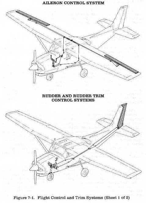
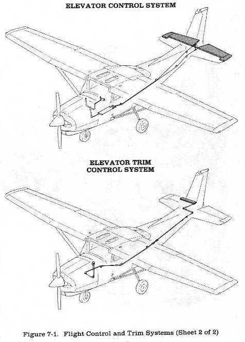
The airplane's flight control system (see figure 7-1) consists of conventional aileron, rudder, and elevator control surfaces. The control surfaces are manually operated through mechanical linkage using a control wheel for the ailerons and elevator, and rudder/brake pedals for the rudder.
Extensions are available for the
rudder/brake pedals. They consist of a rudder pedal face, two spacers and two
spring clips. To install an exten sion, place the clip on the bottom of the
extension under the bottom of the rudder pedal and snap the top clip over the
top of the rudder pedal. Check that the extension is firmly in place. To remove
the extensions, reverse the above procedures.
Manually-operated rudder and
elevator trim is provided (see figure 7- 1). Rudder trimming is accomplished
through a bungee connected to the rudder control system and a trim control wheel
mounted on the control pedestal. Rudder trimming is accomplished by rotating the
horizontally mounted trim control wheel either left or right to the desired trim
position. Rotating the trim wheel to the right will trim nose-right: conversely,
rotating it to the left will trim nose-left. Elevator trimming is accomp lished
through the elevator trim tab by utilizing the vertically mounted trim control
wheel. Forward rotation of the trim wheel will trim nose- down; conversely, aft
rotation will trim nose-up.
 |
 |