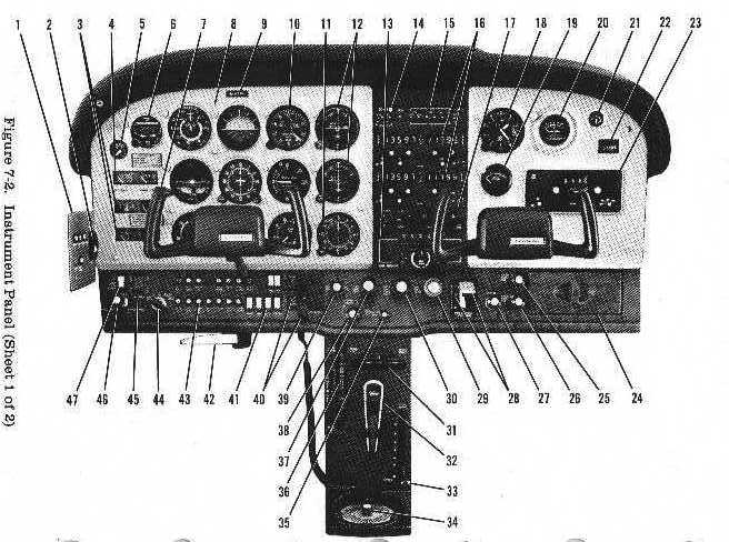
The instrument panel (see figure 7-2) is designed around the basic "T" configuration. The gyros are located immediately in front of the pilot, and arranged vertically. The airspeed indicator and altimeter are located to the left and right of the gyros, respectively. The remaining flight instruments are located around the basic "T". The fuel pressure gage, clock, fuel quantity indicators, ammeter, oil pressure gage, oil temperature gage, cylinder head temperature gage and low-voltage warning light are located to the left of the flight instruments. Avionics equipment is stacked approximately on the centerline of the panel, with the right side of the panel containing the suction gage, economy mixture indicator (EGT), flight hour recorder, and space for additional instruments and avionics equipment. A switch and control panel, at the lower edge of the instrument panel, contains most of the controls, switches, and circuit breakers necessary to operate the airplane. The left side of the panel contains the auxiliary fuel pump switch, engine primer, master switch, ignition switch, general circuit breakers, electrical switches, landing gear indicator lights and landing gear lever. The center area contains the static pressure alternate source valve, and the carburetor heat, light intensity, throttle, propeller, and mixture controls. The right side of the switch and control panel contains the wing flap switch and position indicator, cabin heat and cabin air controls, cigar lighter, and map compartment. A pedestal extending from the switch and control panel to the floorboard, contains the elevator and rudder trim control wheels, cowl flap control lever, and microphone bracket. The fuel selector valve handle is located at the base of the pedestal. A parking brake handle is mounted below the switch and control panel in front of the pilot. The avionics power switch and avionics circuit breakers are mounted on a small circuit breaker panel located adjacent to the pilot on the left cabin sidewall.
For details concerning the instruments, switches, circuit breakers, and controls on this panel, refer in this section to the description of the systems to which these items are related.
| 1. Sidewall
Circuit Breaker Panel 2. Avionics Power Switch 3. Ammeter, Oil Pressure, Cylinder Head, and Oil Temperature Gages 4. Fuel Quantity Indicators 5. Fuel Pressure Gage 6. Digital Clock 7. Auxiliary Microphone Switch 8. Flight Instrument Group 9. Airplane Registration Number 10. Encoding Altimeter 11. ADE Bearing Indicator 12. Course Deviation and Glide Slope Indicators 13. Autopilot Control Unit 14. Marker Beacon Indicator Lights and Switches 15. Audio Control Panel 16. NAV/COM Radios 17. Transponder 18. Secondary Altimeter 19. Economy Mixture Indicator 20. Carburetor Air Temperature Gage 21. Suction Gage 22. Flight Hour Recorder 23. ADF Radio 24. Map Compartment |
25. Cabin Heat
Control 26. Cabin Air Control 27. Cigar Lighter 28. Wing Flap Switch and Position Indicator 29. Mixture Control 30. Propeller Control 31. Rudder Trim Control Wheel and Position Indicator 32. Microphone 33. Cowl Flap Control Lever 34. Fuel Selector Valve Handle 35. Static Pressure Alternate Source Valve 36. Elevator Trim Control Wheel and Position Indicator 37. Throttle (With Friction Lock) 38. Instrument and Radio Dial Lights Dimming Rheostats 39. Carburetor Heat Control 40. Landing Gear Lever and Position Indicator Lights 41. Electrical Switches 42. Parking Brake Handle 43. Circuit Breakers 44. Ignition Switch 45. Master Switch 48. Primer 47. Auxiliary Fuel Pump Switch |